A MMIC with some Muscle
Some folks have built HF gear using MMIC's (gain blocks) as either IF amps, receive preamps or pre-drivers. I've used AG303-86's, MAV-11's, MAR-0685's and even a some hamfest SGA-6486's with few problems and with excellent repeatability. 50 ohm input and output, low external component count, relatively low noise figure and low distortion up to about 20dbm output at 1 db gain compression - what's not to like! The issue I have with these devices is that they're a bit anemic for use use a QRP final amp or as drivers for 5+ watt PA's. Recently, I bought a couple of SV1AFN's (SV1AFN) 1 watt driver, PHA-202+ boards to fill the need for 1 watt (approx.) gain blocks in a few projects. This device/board can , indeed, deliver close to 30 dbm (at 1 db gain compression) output for 10 - 13 dbm input. The down side: the PHA-202+ is relatively expensive (Digikey's single unit price is around $16.64 (US)), current consumption is rather high compared to less stout MMIC's, the driver board doesn't seem to be available, currently, and, of course, the actual device is SMT.
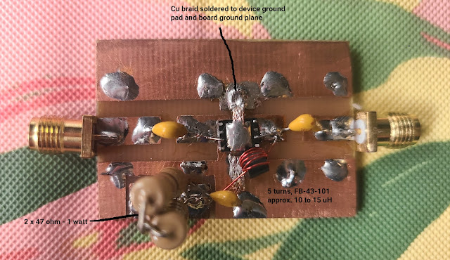
While Makis' driver board is a small thing of beauty, both physically and functionally, I wanted to see if I could duplicate its function with simple construction techniques that average hams use. The PHA-202+ comes in a DL1636 case, ~5mm x 6 mm and contains an exposed "paddle" for grounding and heat transfer. I figured I could fabricate a small, etched board and mount the device dead bug style. I used a very short piece of solder wick as a low inductance ground strap (see photo below) and half baked thermal transfer link. I used very small lengths of #28 magnet wire (thermally stripped and tinned) to make the connections between the input/output pads and the strip lines on the board. No hot plate or toaster oven was needed. I did all the soldering using a fine-tipped iron, aided by a Donegan OptiVISOR.
I built this test amp mostly to the Minicircuits example schematic in their data sheet. I added a hefty 22 ohm dropping resistor (bypassed, of course) in series with the DC feed to lower current consumption from ~350 ma to ~220 ma (at 12 v supply) because of the sketchy heat dissipation setup.I ran a few simple tests. With the board powered-up and connected to my spectrum analyzer (with 50 db attenuation in front of it - just in case), I found no self oscillation. Input SWR was 1.66 to 1 at 20m. Amplification behavior in the middle of the 20m band is shown, below:
1 db gain compression occurred at 28 dbm output. Behavior was essentially identical at 10m. I haven't looked at 2m or 70cm performance to date (don't care that much). My test board produced the same gain as Makis' board, but ~2 db less output at "full bore" - probably because of the lower device operating current in my incarnation. The PHA-202+ passed the "finger test" (barely) after a minute at full output.I'm sure I could get marginally better results using proper SMT construction techniques, but there's no reason to let the good suffer in pursuit of perfection, especially below 30 MHz. BTW - Minicircuits seems to be quite ham radio friendly.....


Comments
Post a Comment