Some Fun with Claude I've had some downtime, recently, courtesy of a couple nasty health issues (no, not cancer). In order to relieve some of the boredom while recovering, I started sorting through some of the electronic "stuff" I've accumulated for projects which, in turn, never seemed to get done. I can across a ESP32-S2 feather - the one with the built-in TFT display - and thought it might be fun to turn it into a cw decoder. (Yes I know such things are no substitute for the ability to copy by ear, but remember, I was bored.) I'm also not a big fan of "vibe coding" but for this exercise I though it'd be interesting to see what Claude could do. Some I told it: 1. Target device is Adafruit ESP32-S2 TFT Feather board. 2. Will be using the current Arduino IDE for editing, compilation and uploading. 3. Input will be raw audio on analog input A5. a. Audio input will be line level (2.00 volts - high impedance). 4. Decoded text will be displa...
Posts
An Ugly POC

This isn't about some skin condition or other annoying medical problem. No, POC means proof of concept in this context. I've always had great interest in the VHF/UHF+ bands, but keeping long-boom stacked yagis in good shape takes more climbing and tower time than I'm willing to invest as a geezer. During the Christmas holiday season, another outlet for experimentation in those bands surfaced: Meshtastic. Metastatic piqued my interest and curiosity for a number of reasons: 1. The devices are essentially small micro-controller boards that also contain a radio chip. These boards aren't very expensive, almost always < $50, <$100 with a nice case. 2. In the US, these devices operate in the 33cm ham band (900 MHz), but can also be used by unlicensed folks, provided certain EIRP restrictions are observed. 3. The firmware for these boards and client software for Android phones, Linux machines, and that other OS are all...

A Look at Two Different Low-Power RF Switches. Omron G5V-1 (left) and HMC349 (right). Small signal relays, like the G5V-1 shown above, are frequently used to change RF paths in home-built amateur radio equipment. You could use two of them to switch an IF strip (with embedded filter, perhaps) from receive to transmit. (I used these in the IF strip of my 6m transceiver.) These devices are cheap (~$2.00 from the usual sources), switch relatively quickly (~5 ms), and aren't too power-hungry. Coil power consumption is rated at 150 mw. Of course, you have to supply your own board and connectors. I've used 3253-type bus switches for similar low-power RF switching tasks with acceptable results, but wondered if dedicated RF switches (like the HMC349 shown above) could work acceptably well for ham radio-type tasks. I found these breakout boards widely available on the usual on-line ...
HF Amplifier Rogue's Gallery

Weather is too nice (but hot, humid, and buggy) to justify a lot of inside time for electronics. Thought I post a gallery of recent HF (broadband) amps. No tube amps, here. Left to right: 2-stage 2N5109/RD15HVF1 - 6W out for 1mW in; push-pull RD15HVF1's - 16W out (KK4DAS's design); push-pull RD30HVF1's - 35W out; push-pull RD70HVF1's - 85 to 100W out; single-ended MRF101 (WA2EUJ design) - >100W output with 50 volt supply. (All the other amps are designed for 12 - 14 volt supply.) I tend to use the HVF devices, even at HF, for higher gain. No power oscillators, yet! I plan to evaluate/optimize IMD behavior for each of these (probably during the winter). One of them will get packaged with a switchable LPF for day-to-day use. Haven't delved into any => VHF amps, recently. I have a selection of these left over from the past, ranging from 25W to 1000W out. Don't need to build any more. ...
Revisiting the LT5517

Some time ago (just before Linear Tech & Analog Devices merged), I requested a few samples of LT's 5517 quadrature demodulator and 5598 quadrature modulator. They happily supplied a few samples of each, but the local LT rep also called me at work and asked if I'd also like to have a dc678a evaluation board ( https://www.analog.com/en/resources/evaluation-hardware-and-software/evaluation-boards-kits/dc678a.html#eb-overview ). Of course, I said, "Hell yes!" and it appeared in the mail soon after (no charge). But then it sat unloved and unused for years until I recently decided to see how well it worked at HF. The 5517 board is the green one in the upper left corner. A 2-channel baseband preamp is the Manhattan-style board next to it. The board below the 5517 board is a split supply boost converter that powers a 100x gain, 2-channel baseband preamp using THAT1510 instrumentation amps. These devices are very similar to the widely used INA217....
A Half-baked Fix for Si5351 Quadrature Issues

In a previous post, I briefly described issues I had preserving quadrature output from an Si5351 board. Allegedly, once a 5351 is programmed to provide a fixed phase offset on a second output, it should maintain that phase shift across frequency excursions, provided the "even divisor" remained unchanged - No PLL reset needed until the a large enough frequency excursion requires a change in the "even divisor". PLL resets caused annoying "pops" in the output of direct conversion front ends that I typically use for phasing-type receivers. I was loathe to include a PLL reset on every frequency change because of that. So, I (and many others) only do a PLL reset when the required integer "even divisor" was changed. Many fewer "pops", but semi-random loss of LO quadrature within a relatively small frequency range. I added a polled front-panel switch to my hardware that I use to manually reset the PLL when my "ear detector" de...
A MMIC with some Muscle
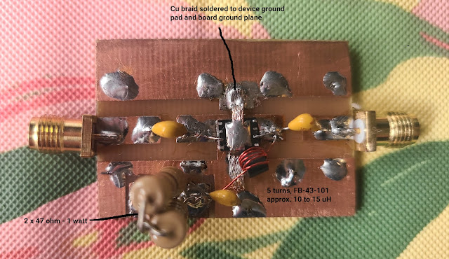
Some folks have built HF gear using MMIC's (gain blocks) as either IF amps, receive preamps or pre-drivers. I've used AG303-86's, MAV-11's, MAR-0685's and even a some hamfest SGA-6486's with few problems and with excellent repeatability. 50 ohm input and output, low external component count, relatively low noise figure and low distortion up to about 20dbm output at 1 db gain compression - what's not to like! The issue I have with these devices is that they're a bit anemic for use use a QRP final amp or as drivers for 5+ watt PA's. Recently, I bought a couple of SV1AFN's (SV1AFN) 1 watt driver, PHA-202+ boards to fill the need for 1 watt (approx.) gain blocks in a few projects. This device/board can , indeed, deliver close to 30 dbm (at 1 db gain compression) output for 10 - 13 dbm input. The down side: the PHA-202+ is relatively expensive (Digikey's single unit price is around $16.64 (US)), current consumption is rather high compared ...